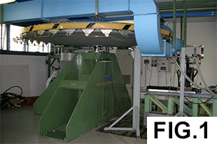
The Current Collection Test Bench (CCTB) is part of our Railway Engineering Lab and enables the testing of a full-scale pantograph collector strip at speed up to 220 km/h with a level of electrical current up to 1000 A in d.c. (direct current) that in some particular cases it is possible to increase up to 1400 A in d.c. and up to 500 A in a.c. (alternating current) 162/3 Hz or 350 A in a.c. 50 Hz. Therefore, the CCTB allows to reproduce the typical European railway power supply.
The typically tests carried out at the CCTB have the aim to evaluate the wear performances of collector strips as a function of the main operation parameters (train speed, collected current and static preload or mean contact force between strip and wire). In particular, Accredited tests ISO 17025:2017 (Accredia) according to the Technical Specification RFI-DMA-IM.LA\ST TE65 can be performed. The aim of these tests is to identify the friction coefficient between pantograph contact strips and contact wire of overhead line and the measurement of wear rate for contact wire and pantograph contact strips.
Concerning research activities, the CCTB is also used to improve current knowledge on the electro-mechanical and thermal phenomena that characterize the current collection and, in general, the interaction between collector strip and contact wire.
The CCTB is composed of two areas: a protected room (bunker) with a protected window for direct visual observation, into which the mechanical part of the test bench is enclosed; and an external area where the control system and the signal acquisition system are located.
Main parts of the CCTB are:
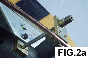
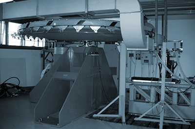
- a fibre-glass wheel, with a 2 m radius, rotating around a vertical axis, with a contact wire elastically connected (Fig.2a) along its perimeter by means of 36 supports. The collector strip is installed on two suspensions linked to a platform moving along the radial direction of the ?bre-glass wheel reproducing the zigzag relative motion produced by the staggering of the contact wire. A controlled a.c. brushless eclectic motor drives the platform. The combination of the peripheral speed of the wheel, which reproduces the train speed, and the transversal motion imposed to the strip (polygonation) results in the total sliding speed between the contact wire and the strip;
- a ventilation apparatus, which conveys an air flow on the strip–wire contact zone, with the goal to replicate the thermal effect of the air flux investing the strip while the train runs.
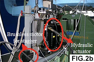
The contact force between the collector and the contact wire is applied by means of a hydraulic actuator installed on the moving platform (Fig.2b). The ventilation apparatus is essential to reproduce the thermal condition in the contact area, which heavily affects the performance of the collector material.
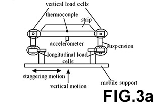
The measurement apparatus equips the CCTB with sensors that are used to measure: the sliding speed of the wheel, more precisely of the strip; both the vertical and longitudinal contact force between wire and strip; the current flow; and the voltage of the test rig electrical circuit. The latest value is used to estimate the occurrence of electrical arcs and, therefore, to quantify an index of loss associated with the occurrence of the arcs themselves.
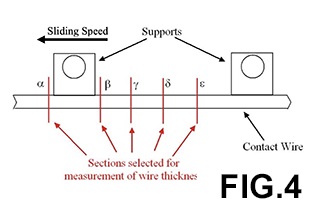
The strip wear rate is estimated from the strip mass difference before and after the test, while contact wire wear rate is estimated by the difference of the thickness between the end and the beginning of the test. The mass of contact strip is measured by means of a digital balance, while the thickness of the contact wire is measured in selected 180 (5×36 supports) sections along the wire(Fig.4) by means of a laser-blade system.